
Links
Download Sunrise Alarm Clock files

Join this project:
To join this project, please contact the project administrators of this project, as shown on the project summary page.

Project Information
About this project:
The proposed project was to design and implement an artificial sunrise alarm clock which gently wakes a person by simulating a sunrise, rather than jarring someone awake with a loud noise, as almost all alarm clocks currently do; similar to the ones found here, here, and here. This sunrise alarm clock can help people start the day in a better mood and feeling more refreshed. This is also good for people that live in apartments, or have bedrooms that do not receive natural light in the morning.
When it is time to awaken, the clock slowly begins to brighten the light on top, simulating a sunrise that can last anywhere from 5 to 60 minutes. The Sunrise begins before the programmed wake up time and becomes brighter until it is at full brightness at the alarm time. In the off chance that the user has not awaken during the Sunrise, then a back up alarm is used to make sure that the user does wake up.
The main goals are to have it be cheaper, and open source than commercial units. This project was originally concieved to fulfill the requirements of a Embedded and real time systems class.
Version 1.0 implimented features:
- The ability to program your own sunrise for 5, 15, 30, 45, or 60 minutes
- A back up audible alarm
- A smart display that dims at night so it won't disturb your sleep
- A nightlight option;
- Choice of 12 or 24 hour time read-outs
- A dot matrix display capable of simple animations, for interesting displays of time and date.
Tools
This project was, from the outset, designed and destined to be an open source, open hardware project. As such every effort was made to use only free/open source tools when available. The project presentations and documents were written with Open Office (http://www.OpenOffice.org). The software component was written and debugged with the freely available Keil Embedded tools that are offered by ARM (http://www.keil.com). The hardware components were designed in Kicad, an open source schematic capture and board layout program (http://www.lis.inpg.fr/realise_au_lis/kicad/). Finally, all documents, schematics, board designs, software, and media applicable to the project are freely available on SourceForge at http://sunrisealarm.sourceforge.net/.
Hardware
Description
The hardware implementation for this project has made use of COTS parts whenever possible. The main micro controller is a STM32F100RB Arm Cortex M3 processor on a STM32VLDISCOVERY prototyping board. All components connecting directly to the prototyping board have been wire-wrapped so that the prototyping board may be removed, and reused in another project if desired. Also, since this was the first prototype of the project, wire-wrapping made it easy to reroute connections to the microprocessor if mistakes were made during the design phase.
The display board was made separate from the main board so that the display could be mounted in the case at an appropriate angle for the user to see. The main board is attached to the display board via two ribbon cables, one that carries the data signals for the rows of the display matrix, and one that carries the column data signals for the display matrix. A schematic was not created for the ribbon cables, as they are trivial.

The display
board contains only the
connectors for the ribbon cables, and the two 8x8 LED display matrix
panels. The current limiting resistors
are places on the main board, as is seen in the schematic.
One mistake that was made in design was the
assumption that the output of the processor was TTL level (5V) when in
fact it
was CMOS (3.3V); this meant that the initial calculation and choice for
current
limiting resistors was incorrect creating a much dimmer display. This was discovered and corrected in the
hardware debug phase.

Going back to the processor, 24 general purpose input output (GPIO) pins are used by the display board, four GPIO pins are used for push button inputs, two GPIO pins are used for differential drive of the piezoelectric speaker, one GPIO is used for power to the zero crossing and ambient light sensors, one GPIO is used for the zero crossing detection, and one GPIO is used for activating the sun lamp. The ambient light sensor input uses the analog to digital converter (ADC) alternate function of the GPIO pin to which it is connected. In total, 34 of the prototyping board's I/O are used.
Special care was taken to be sure to choose pins that are appropriate to the purpose for which they are used. For instance, it was important, that the input from the ambient light sensor was connected to a pin that could be used for ADC. Further it was important to not use Port C pin 14 and 15, as they are connected to the external ceramic oscillator that is used to power the Real Time Clock (RTC) peripheral when the project is unplugged from the wall, and keeping time with the backup battery. However some mistakes where made that could have been avoided with better planning, the choice of input for the zero crossing detection conflicted with push-button two, and hardware interrupts could not be used for both simultaneously, this was accounted for and corrected in software. Further, five of the pins used for the display are also defaulted to be used for the software debugging interface, this creates the situation where either the software could be in debug mode, or the display could be fully active, but not both.
The four push button inputs are normally closed switches that are simply connected to the chip and to ground. Internal pull-ups in the microprocessor peripheral allow the positive edge detection that triggers the interrupt, when the switch is activated. In this configuration, no current limiting was required.
The piezoelectric speaker was another interesting challenge. Again, the assumption that the board puts out TTL logic levels caused an issue where there was not enough swing in voltage to achieve any sizable volume from the speaker in the original design, which had the speaker running from the pin to ground, with a small resistor in series. This problem was overcome by hooking up the speaker to two GPIOs and driving it differentially. This allowed for a 6.6v P-P drive voltage which significantly increased the volume level of the speaker.
The ambient light sensor uses a simple voltage divider type circuit that allows the microprocessor to read a voltage level that varies proportionally with the amount of ambient light in the room.
The zero crossing detector uses, as input, the full wave rectified 6.3VAC signal. The signal is voltage divided, and run through a low pass filter to create a slightly more pulse like output, which is then run through a 2n2222 transistor configured in saturation mode to act as a switch that when turned on, will ground the zero_det input signal to the microprocessor, and when turned off, the sensor_power signal will pull the line back high.
The original proposal
called for a
gutted wal-wart type power supply to run the controller board. However,
it was
easier to use a simple transformer, full-wave rectifier, and a largish
electrolytic capacitor as input to the STM Discovery prototyping board. The prototyping board has a built-on LD1117DT33C low
drop out power regulator, which works quite well with a smoothed 6.3v
input. This also allowed for an
interesting feature, that while not used by the software currently,
could be
used in the future. That is, loss of AC
power could be detected by a missed event in the zero crossing
detector, and
the chip will remain fully powered by the 1000 uF cap for a period of
at least
20mS, which would allow for the chip to power down safely.
More on this in the future work section.
The sunrise lamp is a UL approved fixture purchased at home depot with a 60 watt full spectrum incandescent bulb used to simulate the sun. This is connected to a triac, and then back to the main input power. The triac, in turn, is connected to a diac optoisolator to shield the microprocessor from the possibility of an accidental 120 volts should the triac fail, in an unsafe manner.
The backup battery is a bit of over engineering. Simple, cheap, off-the-shelf parts led to a backup battery of 2 AA batteries in a holder connected to the BATT input of the prototyping board. Later, reading the current draw of the backup power line, is was calculated that with the backup battery is being AA batteries, with a standard capacity of 2700mAh, and the board drawing only 2.2uA while running the RTC, without primary power, the time backup registers and clock would be safe for 140,000 years. This is well longer than the maximum 136 Years the RTC could actually account for without rolling over, and even longer than the batteries themselves could last without complete degradation, given that most alkaline cells would kill themselves in 10 years or so. This means, that the backup batteries never need to be replaced due to them dying from too much current draw from the board.
Two modifications were necessary to be made to the prototyping board. The first was that a protection diode needed to be replaced, due to a mishap with a brass solder sponge. The second was that the BATT input to the chip, was connected to VDD. This was in opposition to the documentation that came with the board. This was corrected with a removal of a zero ohm resistor.
The case for the project is a standard radio shack project case, obviously modified to allow for the push-buttons, sun-lamp mounting, power cord, and display viewing.
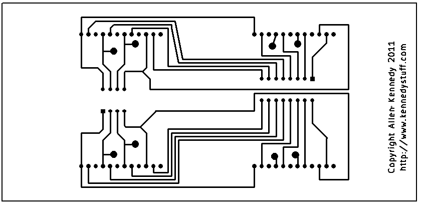
While the main board was wire wrapped, the display board was routed and etched, to provide a more finished look to the display, at least from the inside. It also helped to cut down on all the wiring that was necessary, for the display. The main board, due to its physical size, and requirement for it to be a double-sided board, was a bit too much for simple home fabrication; in the future main board could be routed fully, and etched. Drawing 3 is the copper layer for the display board. The eight largish pads are for surface mounting wire jumpers to connect the last four signals that couldn't be routed on a single layer board.
Bill
of Materials
| Component | Description | Supplier | Part Number | Price |
| Main Board | ||||
| BT1 | 3.2V (2xAA) | Mouser | 12BH324A-GR | $0.57 |
| C1 | 100 pF ceramic | Jameco | 15341 | $0.06 |
| C2 | 1mF | Jameco | 330722 | $0.35 |
| D3 | 2W10M | Jameco | 279515 | $0.55 |
| D4 | 1N4001 | Radio Shack | 276-1653 | $0.12 |
| F1 | 1 Amp | Jameco | 1711947 | $0.95 |
| J1 | EDISON_PLUG | Junk Box | $0.50 | |
| LP1 | LAMP | The Home Depot | $5.99 | |
| P1 | CONN_2 | none | ||
| P2 | CONN_1 | none | ||
| P3 | CONN_1 | none | ||
| P4 | DIL16 | Jameco | 37373 | $0.17 |
| P5 | DIL8 | Jameco | 51571 | $0.12 |
| Q1 | 2N2222 | Mouser | 863-P2N2222AG | $0.36 |
| R1 | CDS001-8001 | Jameco | 202403 | $0.89 |
| R2 | 10k | Jameco | 691104 | $0.02 |
| R3 | 220 | Jameco | 690700 | $0.02 |
| R4 | 220 | Jameco | 690700 | $0.02 |
| R5 | 10k | Jameco | 691104 | $0.02 |
| R6 | 1k | Jameco | 690865 | $0.02 |
| R7 | 4.7k | Jameco | 691024 | $0.02 |
| R8 | 470k | Jameco | 691500 | $0.02 |
| R9 | 10k | Jameco | 691104 | $0.02 |
| R10 | 220 | Jameco | 690700 | $0.02 |
| RP1 | 56 Ohm | Mouser | 652-4116R-1-56 | $0.52 |
| RP2 | 56 Ohm | Mouser | 652-4116R-1-56 | $0.52 |
| SP1 | Piezoelectric Speaker | Jameco | 2098558 | $1.19 |
| SW1 | MENU | Jameco | 26649 | $0.59 |
| SW2 | UP | Jameco | 26649 | $0.59 |
| SW3 | DOWN | Jameco | 26649 | $0.59 |
| SW4 | BACK | Jameco | 26649 | $0.59 |
| T1 | 120:6.3 VAC | Jameco | 102163 | $6.95 |
| U1 | STM32-DISCOVRY | Arrow | STM32-DISCOVRY | $10.34 |
| U2 | OPTO-TRIAC | Mouser | 512-MOC3021M | $0.67 |
| Display Board | ||||
| U3 | BT136D | Mouser | 771-BT136-600D | $0.35 |
| D1 | 8X8_LED_MATRIX | Futurlec | LEDM88RGCA | $3.90 |
| D2 | 8X8_LED_MATRIX | Futurlec | LEDM88RGCA | $3.90 |
| P1 | DIL16 | Jameco | 37373 | $0.17 |
| P2 | DIL8 | Jameco | 51571 | $0.12 |
| Misc. | ||||
| Case | Radio Shack | 270-1809 | $6.99 | |
| PCB | Radio Shack | 276-1394 | $2.99 | |
| solder | various | $1.00 | ||
| wire | Radio Shack | 278-503 | $2.00 | |
| misc. | screws, heat shrink, etc | various | $3.00 | |
| total | $57.70 | |||
Software
Description

RTOS
LED Matrix Display
Real Time Clock
Buzz Alarm
The Buzz task is blocked during normal time, only when the alarm flag is set will this task been signaled and resumed. Two GPIO pins have been turned on/off in an opposite order to generate the alarm buzz.
Zero Crossing / Sun
lighting
Zero crossing circuit provides an input pulse when 60HZ AC cross the zero line. Another internal timer counter is kept triggering at a higher frequency. When zero crossing ISR triggered, it reset the counter. Only when that counter reaches the calculated duty cycle counter number inside that timer ISR will the pulse been sent out to latch the triac in one semi AC cycle.
The way triac circuit works is like a latch. If it has been turn on, it will be latched until the voltage crossing the zero line again. Then it will reset it self until another input pulse hit the triac.

Due to the vision requirement of the LED module and the bulb light circuit. Those two tasks need to be hard real time scheduled to ensure no flicking either on the LED module or the bulb. Both tasks are called inside of the ISR. Because it requires a lot of CPU run time to dim the LED by adjust the duty cycle without a real PWM peripheral. A preemption priority scheme is implemented here. The triac ISR has a higher priority than LED ISR and would be able to block the LED ISR while it’s running. The Zero Crossing ISR has the highest priority and will be able to block any running task/ISR to ensure the sync with 60 Hz AC input.
The whole system is priority based. Zero crossing ISR has the highest priority. Follow by the triac ISR, LED ISR, and then the Main Task. The RTC Task and Buzz Task have the lowest priority and they are blocked most of the CPU run time.

For the hardware, one piece of future work is self evident; the main board needs to be routed. Also, a standalone temperature sensor could be added to the system; maybe just a simple thermocouple and a resistor into one of the ADC lines.
The volume of the backup alarm, while adequate, could be made louder. It is just barely loud enough to wake the user, having it a bit louder would be good. This could be possible through the use of both secondary taps off the transformer, that provides a good 14V P-P, that could be rectified, run through a smoothing cap, and used through a mosfet H bridge to apply full forward and reverse voltages creating a 28V P-P earsplitting 90db+, which should be plenty enough to wake any heavy sleeper, and possibly their neighbors. The possibility is there in the hardware; just a few more components could get that to work.
Finally, for hardware, the backup battery could be changed to a coin cell. A CR2032, or the like could adequately power the backup circuitry for years, and might never need replacing.
For the software, due to the limitation of resource and time, a simple way to directly connect the GPIO with the LED modules was used, which could have used a MUX to save a lot of pins. Also if time allowed, a DMA should be used to transfer the display data from memory to GPIO without CPU intervention, which could save a lot of CPU run time.
Further work could be done in concert with the hardware feature that allows the chip to be fully powered after the unit is unplugged from the wall, for a period of at least 20ms. This could be used to store time in the backup registers, and upon power up, know how long the unit was unplugged for, which may be useful. Or perhaps it could be used, with some additional circuitry, to alert a user via text message, or tweet, that power was lost.
©Copyright 2011 Allen Kennedy, All Rights
Reserved,
website written with the help of KompoZer
About SourceForge - Legal - Help
This file last modified 05/03/11
Free Web Counter